What is battery screening used for?
Li-battery screening appears at many stages of the battery value chain, from research and development to assessment for second use. During R&D, it can help select and validate battery chemistries. Screening also supports cell selection for particular applications and evaluation of pilot studies.
The process often includes electrical testing through charge–discharge cycles. Measured and calculated parameters can then be compared over time using consistent criteria.
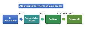
A staged selection process can begin by tracking capacity and internal resistance, measured using a defined method, across multiple cells. Selected cells may then undergo more detailed EIS or dQ/dV analysis. The original article’s manufacturer background is EIS and Battery Screening.
Basic measurements and EIS in one workflow
Electrochemical impedance spectroscopy examines the cell’s frequency-dependent response. An EIS-capable cycler can combine charge–discharge cycling and impedance measurements in one program, reducing reconnections. This does not mean that every test can be performed arbitrarily and simultaneously on the same cell.
EIS is not always a measurement lasting only a few minutes: one period at 10 mHz lasts 100 s. Three periods require five minutes for just one frequency point, excluding settling time. The frequency window therefore also determines screening throughput.
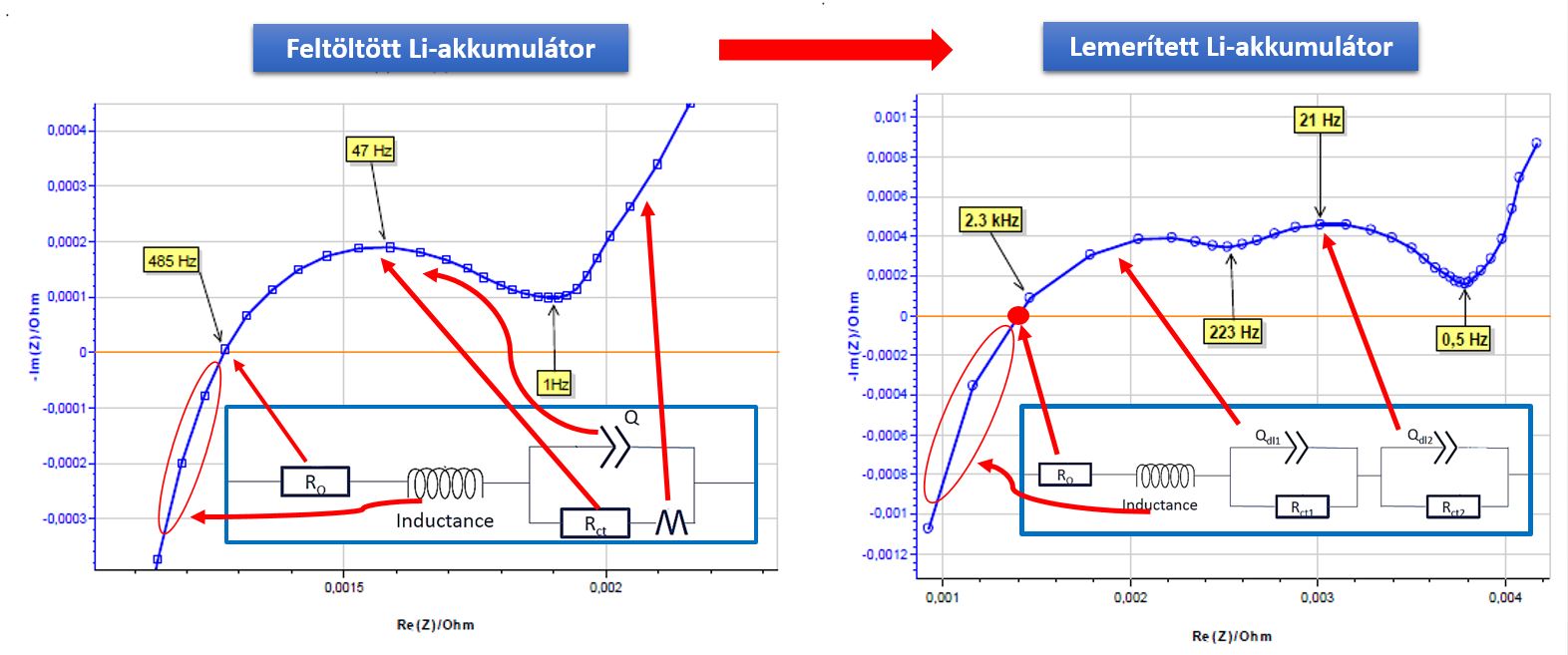
The retained figure illustrates different charge states; it is not a universal fault threshold or circuit model for every cell. The relationship between impedance and state of charge depends on chemistry, and an empirical correlation alone does not establish a physical mechanism. BioLogic White Paper 1: studying batteries with EIS.
Raw spectra remain useful for later analysis when their measurement conditions have also been retained. However, fitting cannot recover an unmeasured frequency band or correct an inappropriate cell state retrospectively.
A protocol for comparable screening results
The following editorial checklist provides a starting point for designing your own protocol:
- Sample and history: identifiers, chemistry, format, batch, cycle count and conditioning. Do not classify different cell types using one shared milliohm threshold.
- SOC: record the target and how it was reached, the capacity reference used, and the charge or discharge direction.
- Temperature: use the same setpoint and sensor placement; record measured cell temperature and the criterion for thermal settling.
- Rest: document duration and the time window used to assess voltage drift. Elapsed waiting time alone should not establish stability.
- EIS: match frequency sequence, excitation mode, amplitude and its definition, period count and wiring. Check excitation and data quality in a pilot measurement.
- Decision feature: specify whether you compare Re Z at a given frequency, impedance magnitude or a fitted parameter. These quantities are not interchangeable.
During charge or discharge, cell composition changes, so the system cannot be assumed time-invariant at every frequency. Operando EIS requires separate methodological checks and cannot automatically replace a screening spectrum measured after rest. BioLogic AN69-2: non-stationary EIS.
Original decision example: repeat before classifying
Suppose identical cell types are tested under an internally validated protocol at 50% SOC and 25 °C, using Re Z(1 kHz) as the observed feature. A previously acceptable reference group has a median of 18.0 mΩ. Cell A measures 18.4 mΩ and cell B 22.5 mΩ: deviations of 2.2% and 25.0%, respectively.
This does not justify automatic rejection. In our example, after restoring the contact and re-establishing the test state, B measures 18.8 mΩ, a deviation of only 4.4%. Retain the first result with its measurement note and route the cell for further checks. A single repeat does not prove that contact resistance caused the entire difference, or that the cell is definitely acceptable.
The 18 mΩ value and these percentages are fictional teaching values. Establish acceptance limits from your own sample population, measurement uncertainty, repeatability and application requirements. EIS screening alone is not a complete assessment of capacity, lifetime or safety.
The historical BCS-800 example and present-day configuration
The original 2020 article presented the BCS-800 series. BCS-805, BCS-810 and BCS-815 modules offered eight independent channels, with maximum per-channel currents of ±150 mA, ±1.5 A and ±15 A, respectively. These are historical details rather than a description of the complete current portfolio.
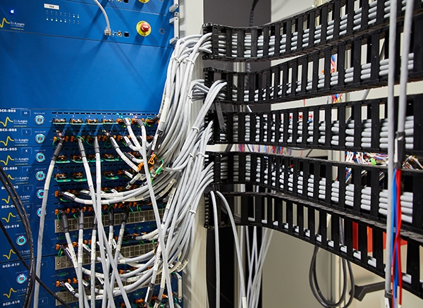
The optional BCS-800 FRA enabled EIS over 10 kHz–10 mHz. Consult the archived manufacturer’s BCS-800 brochure for details. For a new purchase, confirm the specific model, channel count and EIS option in the BCS-900 family; do not transfer the old system’s specifications automatically to a new configuration.
Related planning guides cover EIS data quality, battery internal resistance and EIS fundamentals.