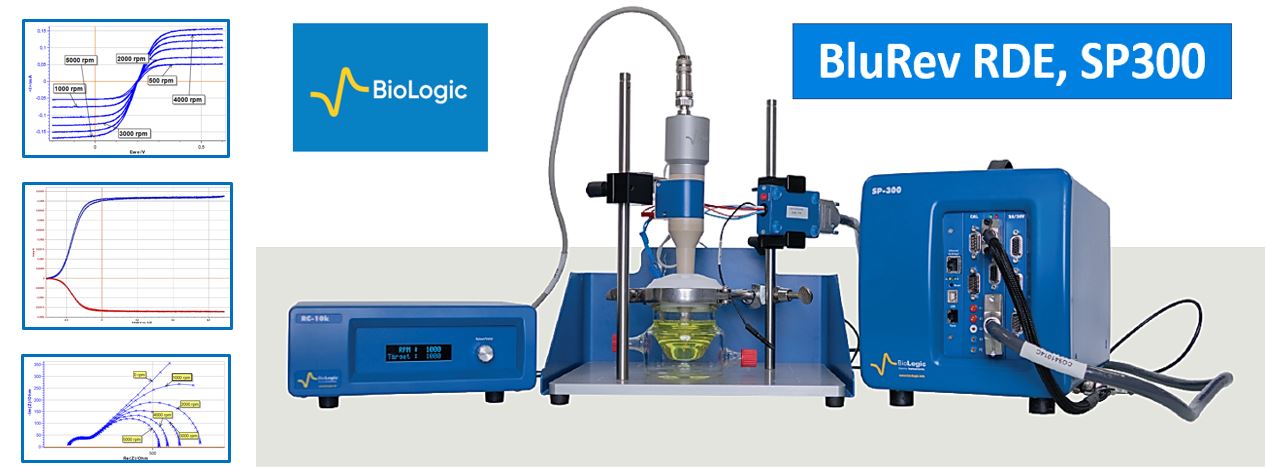
Introduction to the rotating disk electrode
A rotating disk electrode (RDE) creates controlled convective mass transport. The ideal Levich model assumes laminar flow, suitable geometry and steady limiting current. Uniform surface flux is not automatic for every coating or operating condition. Varying rotation rate helps distinguish reaction kinetics from transport.
RDE can investigate kinetics and diffusion. Detecting products separately often requires a rotating ring-disk electrode, RRDE. The signal alone need not identify a product uniquely.
BluRev and an appropriate BioLogic potentiostat configuration support these experiments. EC-Lab can coordinate rotation and electrochemical sequences; electrode preparation, hydrodynamics and model validation remain part of the experiment.
Why use RDE and RRDE?
Rotation establishes a reproducible steady transport regime, not thermodynamic equilibrium. Solution approaches the disk axially and moves outward along its surface.
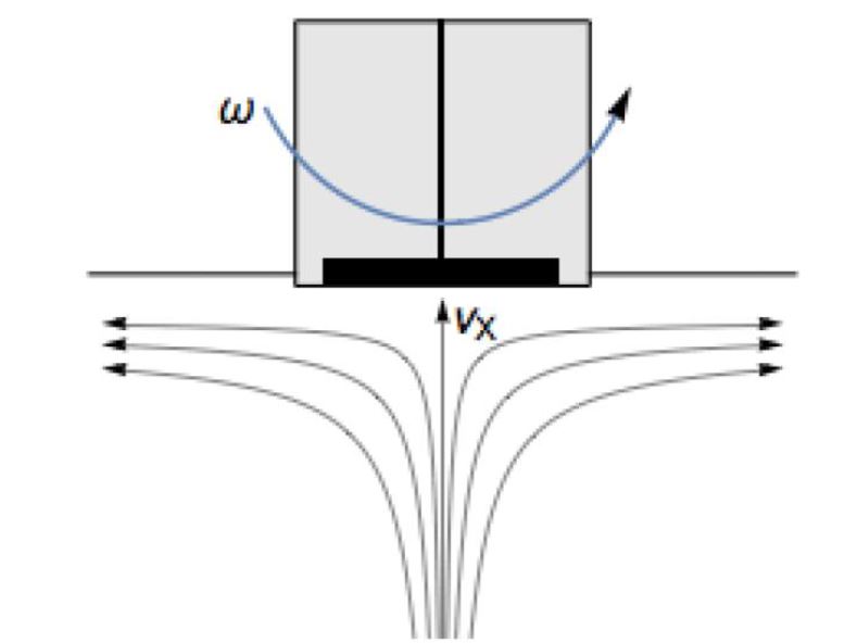
The Levich description relates diffusion-limited current density to the square root of angular rotation rate. For oxidation of R:

For reduction of O, using the corresponding signed current convention:

Here n is electron number; F is the Faraday constant; Rbulk and Obulk are molar concentrations in mol/cm³; D values are diffusion coefficients in cm²/s; ν is kinematic viscosity in cm²/s; and ω is angular rotation rate in rad/s. Current density is I/A. Under the model assumptions, the rotation dependence permits inference of diffusion coefficients or, with known diffusion, concentration.
Koutecký–Levich analysis separates a kinetic-current contribution and can support estimation of kinetic parameters such as k⁰ and α with an appropriate reaction model. EIS at different rotation rates offers another route to testing kinetic and diffusion models.
RRDE adds an independently controlled ring around the disk. Products formed at the disk are transported toward the ring, where an appropriate reaction detects them. Applications include multistep mechanisms, intermediates and transport, subject to collection and reaction assumptions.
These methods are useful in electrocatalysis, fuel-cell and electrolyzer research, photoelectrochemistry, batteries, corrosion/coatings, sensors, electrodeposition, bioelectrochemistry, pharmaceutical research and electroanalysis.
BluRev equipment and archived configurations
The original RDE package 094-RC/RDE includes a controller and rotator, with electrode tips selected separately. The RRDE package 094-RC/RRDE similarly combines an RC-10k controller and ring-disk rotator. Ordering codes below are retained from the archive; confirm availability and compatibility before ordering.
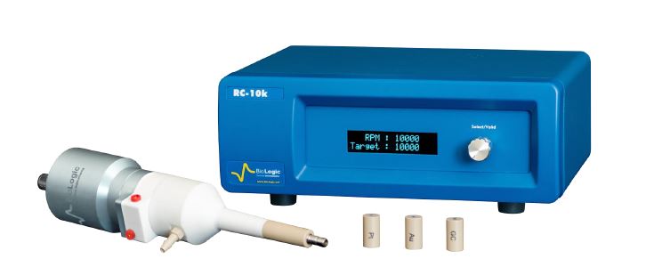
The manufacturer specifications list:
- Rotation: 100–10,000 rpm for RDE; RRDE maximum 9000 rpm.
- Accuracy: ±1 rpm over the specified range.
- Runout: below 0.1 mm.
- Minimum control increment: 10 rpm; measurement resolution: 1 rpm.
- Auxiliary input/output for external control/measurement.
- Operating temperature: 10–40 °C.
Electrode tips
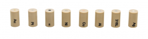
The archived tips use PEEK bodies and M6 mounting threads. Material compatibility must still be checked against the electrolyte. Listed RDE options were:
- Pt 99.9%, 2 mm, 094-Pt/2; Au 99.9%, 2 mm, 094-Au/2.
- Glassy carbon, 3 mm, 094-GC/3; glassy carbon, 5 mm, 094-GC/5.
- Ag, Cu, Ni and Al, each 99.9%, 3 mm, respectively 094-Ag/3, 094-Cu/3, 094-Ni/3 and 094-Al/3.
- 316L stainless steel, 3 mm, 094-316L/3.
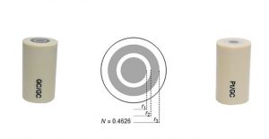
Archived RRDE options were 094-GC-GC, with a 1 mm-wide glassy-carbon ring and 3 mm glassy-carbon disk, and 094-Pt-GC, with a platinum ring and glassy-carbon disk, both with PEEK bodies and M6 threads. The illustrated radii are r1 = 1.5, r2 = 2 and r3 = 3 mm; the archive states theoretical collection N = 0.4626.
Expanded setup and bipotentiostat control
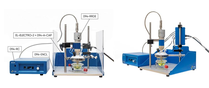
An expanded setup can include a cell, stands, cable/contact supports and protective enclosure, in addition to the rotator and controller; the original illustration excludes the potentiostat.
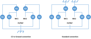
RRDE requires control of two working electrodes: disk and ring. A suitably equipped two-channel SP-300 is one possible configuration. Shared-cell operation requires compatible connections and grounding to avoid unwanted current paths.
The original discussion presents isolated/floating channel arrangements and CE-to-ground arrangements. These must be implemented according to the actual instrument manual, not by joining arbitrary channels. The manufacturer connection guide provides background.
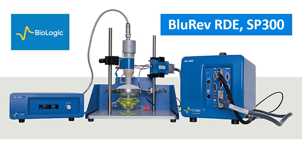
A typical experiment scans the disk potential while holding the ring at a potential suitable for oxidation or reduction of a disk-generated species. EC-Lab provides dedicated coordinated sequences. Set the potential limits, rotation and acquisition requirements for the chemistry rather than treating historical screenshots as universal recipes.
Levich experiment and analysis
The archived experiment used equimolar K₃[Fe(CN)₆] and K₄[Fe(CN)₆], each 0.005 mol/L, in 0.1 mol/L KCl. Temperature was 20 °C; kinematic viscosity was taken as 10⁻² cm²/s. The working electrode was a 2 mm Pt disk, 094-Pt/2.

The illustrated redox couple is ferricyanide/ferrocyanide. The historical EC-Lab workflow selects the Levich technique and configures its limits:
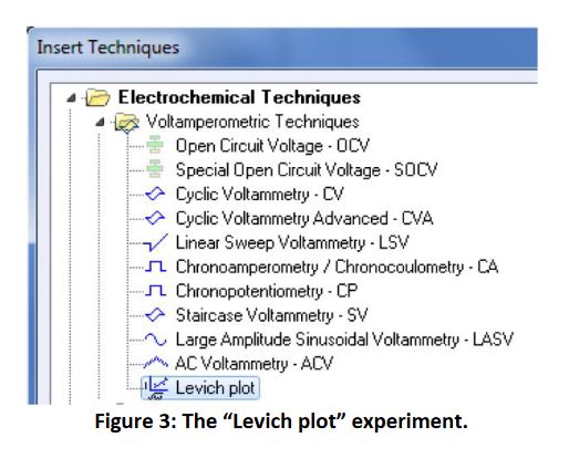
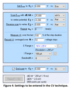
Rotation rates were 500, 1000, 2000, 3000, 4000 and 5000 rpm. The original example described an OCV around 0.1–0.3 V versus Ag/AgCl; this is a dataset-specific indication, not a calibration standard.
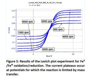
Hysteresis at lower rotation suggests that steady conditions were not reached, potentially because the potential sweep was too fast. Reduced hysteresis at higher rotation in this example does not establish equilibrium.
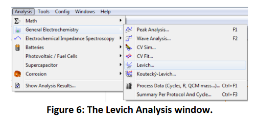
The historical Analysis menu provides the Levich tool. Enter area, concentration, viscosity and other required quantities before calculating the plot:
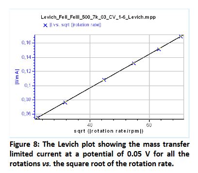
Reported diffusion coefficients were 6.8 × 10⁻⁶ cm²/s for [Fe(CN)₆]³⁻ and 5.9 × 10⁻⁶ cm²/s for [Fe(CN)₆]⁴⁻. The anodic analysis used a reported plateau near 0.595 V, with reference and conditions belonging to that example. The original corrupted species labels have been repaired. If D is independently known, the corresponding analysis can instead estimate concentration.
Koutecký–Levich extrapolation
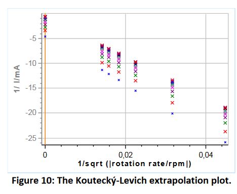
At selected potentials, plot inverse current or current density against inverse square-root rotation rate. In the simple model:
1/I = 1/Ik + 1/Ilim.
Extrapolation to ω⁻¹ᐟ² = 0 gives 1/Ik, whose reciprocal is the kinetic current. An rpm-based horizontal axis changes the prefactor relative to rad/s; units must be consistent.
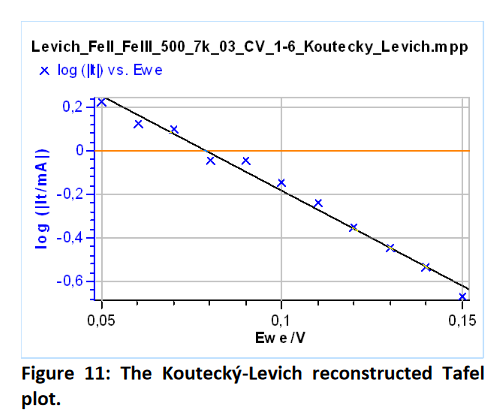
A plot of log|Ik| against E can support Tafel analysis. In a suitable kinetic model, the slope relates to α and extrapolation with a known formal potential can constrain k⁰.
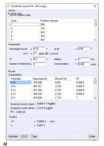
Software estimates parameters within the chosen model. Fit uncertainty is not a substitute for uncertainties in area, concentration, viscosity and rotation rate.
Electron-number inference and slope limitations
The archived quasi-reversible slope expression is retained:
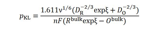
Its dimensionless potential is ξ = nF(E − E°′)/(RT), where E°′ is the formal potential in the stated medium. The quasi-reversible slope can depend on potential. The following simplified limiting expression pertains to irreversible reduction:
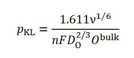
In that limit, slopes may be potential-independent and the Koutecký–Levich lines parallel. Do not infer electron number merely from a convenient straight line in a complex catalytic system: D, concentration, viscosity, reaction order, area and mechanism assumptions matter.
RDE impedance measurements
Levich and Koutecký–Levich methods use rotation-dependent polarisation curves. Impedance fitting at stationary or rotating electrodes can provide complementary parameter estimates if the model is identifiable. Applications include electrocatalysis, fuel cells, corrosion, sensing, electroanalysis and energy storage.
BioLogic AN66 describes the archived EIS experiment. It used the solution described above, BluRev and a VMP-3. Other configurations require independent checks of control, EIS options and channel wiring.
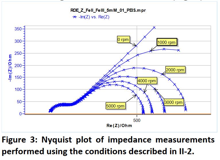
In the displayed dataset, the high-frequency region associated with charge-transfer resistance changes little with rotation. At zero rotation, the lower-frequency response has a semi-infinite diffusion contribution. Under rotation, convection modifies this region and the low-frequency real impedance decreases as rotation increases.
ZFit can fit a suitable equivalent circuit. Parameter values become physical estimates only when the circuit meaning and input assumptions are justified.
Stationary electrode: 0 rpm
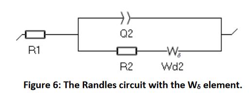
The archived analysis uses a Randles-type circuit with a Warburg element:
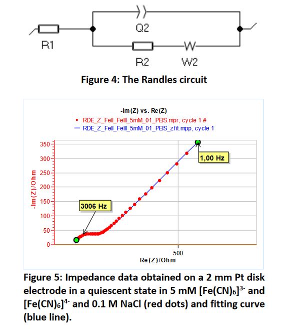
R1 is solution resistance between working and reference electrodes; R2 is charge-transfer resistance. Q2 is a constant-phase element representing nonideal double-layer behaviour, not a capacitance directly when a2 differs from 1. W2 represents diffusion.
The original Randomize + Simplex fit without weighting reports R1 = 139.9 Ω, Q2 = 6.057 × 10⁻⁶ F·s^(a2−1), a2 = 0.821, R2 = 79.14 Ω, σ2 = 896.8 Ω·s⁻¹ᐟ² and χ² = 97.78 Ω². Its derived DX is 7.13 × 10⁻⁶ cm²/s. These are historical fit results, not a new validation.
Rotating electrode: 1000–5000 rpm
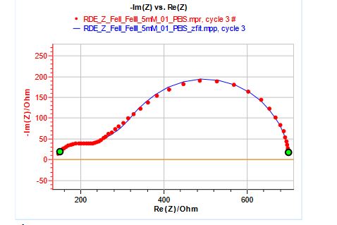
A semi-infinite Warburg element alone does not capture the entire convective-diffusion response. The archive compares two alternatives:
Wδ: a finite-layer/Nernst approximation with concentration varying within a diffusion layer and held constant outside it.
Winf: the RDE convective-diffusion description discussed in AN66, historically introduced in EC-Lab 11.25. It represents the distributed concentration profile more closely for that model.
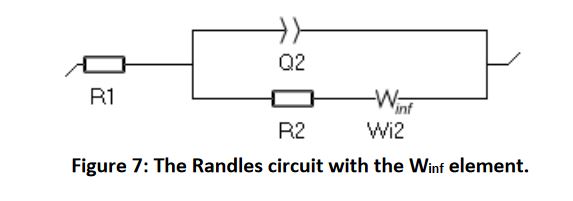
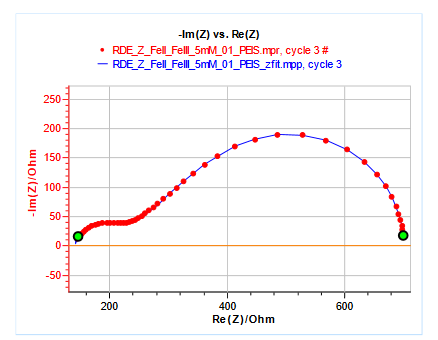
Winf provided the more appropriate approximation in this example; this is not a universal ranking of fitting accuracy. Directly reported D still depends on geometry, known inputs and identifiable fitting. Wδ can be appropriate for finite diffusion domains, including suitable thin-layer or membrane models.
RRDE experiment with two working electrodes
The original discussion names VSP-300, BP-300, VMP-3 and VMP-300 systems. These are historical examples, not a current compatibility list. The original account attributes the rotating ring-disk concept to Frumkin and Nekrasov in 1959. RRDE uses an electrically insulated ring and disk, often of different conductive materials, separated by PTFE or PEEK.
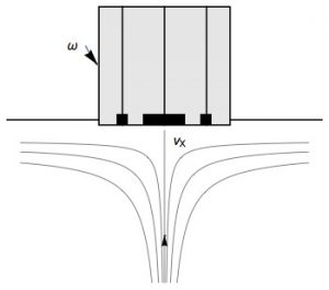
Rotation moves solution outward from the disk toward the ring. With independently controlled potentials ED and ER, an illustrative reaction pair is:
- Disk at a suitable oxidising potential: X → Y + ne⁻.
- Ring at a suitable reducing potential: Y + ne⁻ → X.
The electrode materials and detection potentials must support the intended reactions. Merely choosing ER below ED is not sufficient proof of selective detection. A shared reference and counter electrode are used in an appropriate bipotentiostat connection.
Archived configuration
The reported experiment used 0.005 mol/L ferrocyanide in 0.5 mol/L KCl, a Pt counter electrode and Ag/AgCl reference. A VMP-3 with EC-Lab 11.21 used the CE-to-ground configuration.
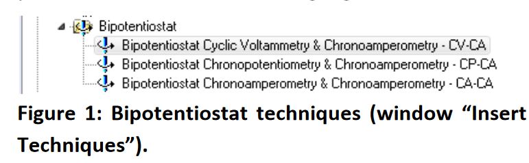
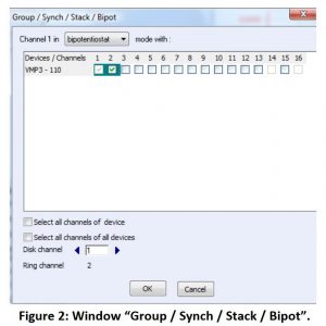
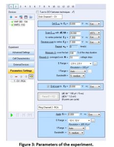
The selected technique was CV-CA: a cyclic scan at the disk and chronoamperometric detection at the ring. Two compatible channels were grouped through the historical “Edit → Group / Synch / Stack / Bipot” menu:
Results and collection efficiency
At 2000 rpm, the source reports a disk scan between 0 and 1 V relative to its OCV while the ring was held at 0 V relative to OCV. Those offsets and the separate electrodes’ reference definitions must be checked in the original method before reproduction. Ferrocyanide is oxidised at the disk and a fraction of ferricyanide transported to the ring is reduced there.
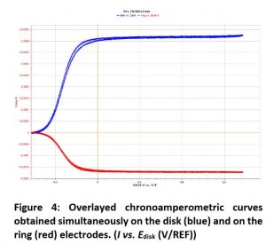
Blue denotes disk current and red ring current. The coordinated experiment gave the reported limiting-current ratio N = −IRing/IDisk = 0.405, compared with a theoretical 0.425 for that experiment. The relative difference is about 4.7%; agreement cannot be certified without uncertainty information.
Units, collection and practical checks
The limiting current magnitude is |Ilim| = 0.620 nFA D^(2/3)ν^(−1/6)ω^(1/2)c in the laminar steady transport limit. The earlier equation images express current density, so omit A. ω = 2π × rpm/60: 1600 rpm corresponds to 167.55 rad/s. Substituting rpm directly into the rad/s expression gives the wrong prefactor.
The ratio N = −IR/ID assumes matched electron numbers, suitable reverse detection, background correction and stable product transport. The archived geometric value 0.4626 and the later experiment’s 0.425 may refer to different assemblies; they are not treated as interchangeable calibrated values for one tip. Calibrate with a suitable known redox system. Our arithmetic example: ID = 100 µA and IR = −40 µA gives N = 0.40.
Record tip geometry, exposed area, solution composition, temperature/viscosity, rotation units, background correction and fitting ranges. EC-Lab coordinates measurements and analysis; it does not eliminate model checks. Further sources: AN56 and our EIS fitting guide.