The electrochemical cell is part of the experiment. In a conventional three-electrode arrangement, working, counter and reference electrodes contact the electrolyte and connect to the instrument. Cell dimensions, materials, lid, temperature control and electrode positions matter. Not every experiment needs three electrodes: a complete battery cell can be measured in a two-electrode configuration.
The original article introduced representative BioLogic cells and accessories. Its photographs and component list are retained, but they are not a universal packing list for current quotations.
A standard electrochemical cell
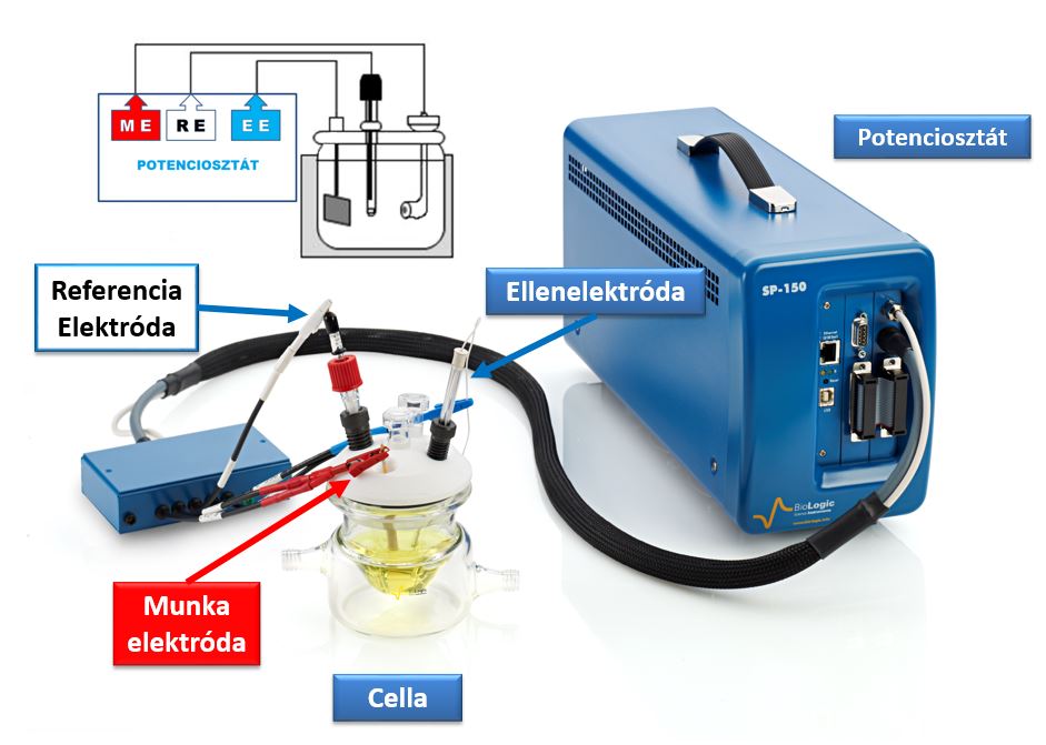
The historical photograph shows a three-electrode cell connected to an SP-150. Red identifies the working electrode, blue the counter and white the reference in this illustration; these are not universal cable colours. See how a potentiostat works for electrode roles.
A temperature-control fluid can circulate through the external jacket. Verify temperature at the cell too: the thermostat setpoint alone does not prove uniform electrolyte temperature.
Lid ports accommodate gas inlet/outlet tubes, electrodes or other sensors. The illustrated lid has five ports. Diameter, seals and clearance between accessories matter alongside port count. Confirm the chosen arrangement against the current manufacturer cell page.
Scroll the table horizontally on narrow screens.
| Code | Qty | Component |
|---|---|---|
| EL-A-001 | 1 | 80 mL cell vial |
| EL-A-003 | 1 | PTFE cap with five ports |
| EL-A-004 | 1 | PTFE ring, silicone encapsulated, 10.2 cm diameter |
| EL-A-005 | 1 | Cell collar with clamp |
| EL-A-009 | 1 | Platinum counter electrode |
| EL-A-016 | 1 | Purge tube |
| EL-A-008 | 1 | Bridge tube for a 6 mm OD reference electrode |
| A-013430 | 1 | RE-2BP calomel reference, 92 mm long, 6 mm OD |
The historical kit list included a calomel reference and a platinum counter electrode; the working electrode was selected separately. For a new order, confirm the reference, electrodes and actual package contents against electrolyte and sample requirements. Retained codes help identify the earlier system.
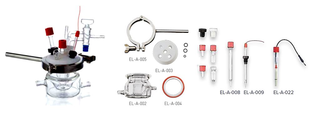
A cell stand and stirring were listed as accessories. Integration with a BluRev rotating-electrode system requires checking the vessel, lid, shaft and mounting geometry. The local BluRev overview describes the system; compatibility must be established for the actual configuration.
Small-volume cells
Small cells are useful with precious electrolytes, limited sample quantities and small working-electrode areas. Smaller volume is not automatically better: the electrodes, reference and gas tubes still need space.
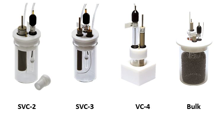
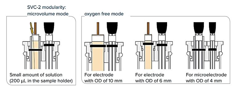
In the retained product example, SVC-2 is modular and accommodates different electrode forms. SVC-3 is listed for 5–20 mL with a 6 mm outer-diameter working electrode; VC-4 serves 1–3 mL working volumes with 6 mm OD electrodes. The Bulk electrolysis cell is a 100 mL example. Nominal vessel capacity and usable working volume can differ. Manufacturer configurations and kit details.
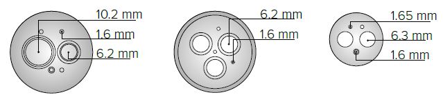
PTFE lid hole patterns and electrode-holder adapters determine what fits. OD refers to the electrode body’s external dimension, not necessarily the active disk diameter.
Working electrodes
The reaction of interest takes place at the working-electrode surface. Material, geometric and actual active area, surface preparation and history all affect the result. The retained illustration shows different electrode lengths and diameters.
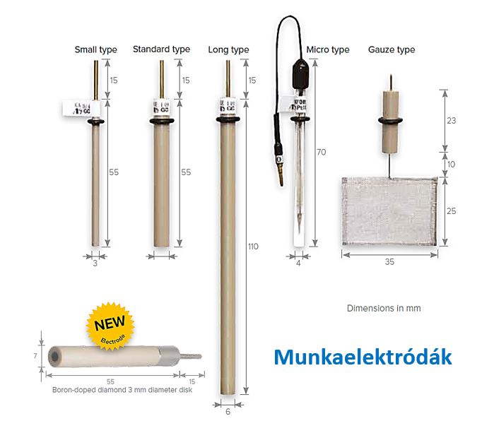
Listed materials included BDD (boron-doped diamond), carbon, Pt, Au, Ag, Pd, Ni, Cu and Fe, plus empty bodies for carbon paste. These are not “nine metals”: carbon and diamond are not metals. The historical 10 µm–5 mm range covered different products, not every material in every size. Check the particular working-electrode specification.
Our geometric example uses a flat circular disk of diameter 3.0 mm: A = πd²/4 ≈ 0.0707 cm². At 1.0 mA, geometric current density is 14.1 mA/cm². Using a 6 mm casing diameter instead would give four times the area and one quarter of the current density. This calculation does not establish microscopic active area.
Counter electrodes
The counter electrode closes the current path and also hosts a reaction. Select its material against medium, expected current, polarisation and products. Larger area can reduce current density, but an area ratio alone does not prove suitability.
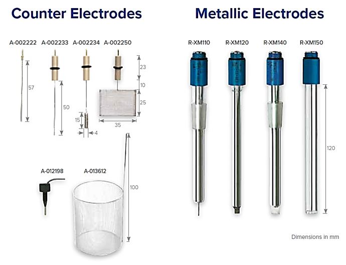
Our suggested design check asks whether counter-electrode products can reach the sample, whether a separated compartment is needed, and whether its resistance fits the instrument’s output headroom. Establish connections and limits from documentation for the actual cell.
Reference electrodes and potential scales
A reference supplies a stable comparison potential under specified solution and temperature conditions. “Fixed” does not mean identical under all conditions. Aqueous versus non-aqueous medium, junction potentials and contamination risk affect selection.
The historical list includes calomel, Ag/AgCl and mercury/mercury(I) sulfate references. The latter is Hg/Hg₂SO₄, not Hg/HgSO₄. There is no universal reference covering every electrolyte and application. Manufacturer reference-electrode selection.
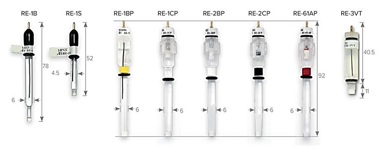
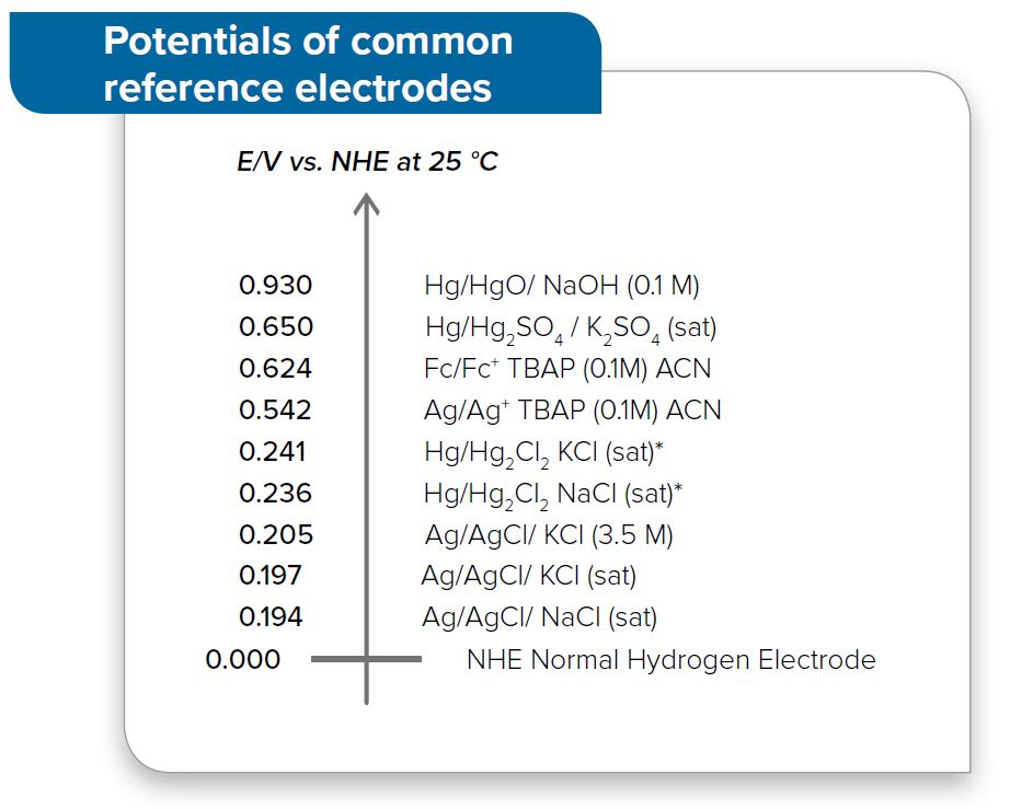
The figure applies to its stated electrolytes at 25 °C. Before converting potentials, record reference type, filling solution and concentration, temperature and destination scale. Our reference-electrode guide explains verification steps.
What information is needed to configure a cell?
This editorial checklist turns the historical product examples into experimental requirements:
- Electrolyte, solvent, available volume and material compatibility.
- Working-electrode material, active dimensions, complete external dimensions and placement.
- Reference, counter electrode, separation and expected current/voltage.
- Temperature, stirring, gas handling and sensor clearance.
- Cleaning, repeatable positioning and connections to the existing instrument.
Use the local systems and accessories catalogue and contact the representative to establish the specific arrangement.