BioLogic Premium internal boosters
The original phrase “self-install” means a compatible internal booster that a user can install following the manufacturer’s procedure. It does not mean automatic installation or insertion while operating.
BioLogic offers internal boosters for compatible Premium potentiostat/galvanostats. Applications include batteries, fuel cells, photovoltaics and electrolysis. Different cell requirements call for different current/voltage windows:
- ±1 A / ±48 V
- ±2 A / ±30 V
- ±4 A / −3 to +14 V
- ±10 A / −1 to +6 V
A modular system that can follow changing experiments
Premium boosters occupy positions inside the instrument chassis, alongside potentiostat boards. A compatible instrument can therefore be reconfigured as the cell under investigation changes. For example, a channel can work with a 1 A board for one experiment and a 10 A board for another.
Expansion can take place after purchase, following the manufacturer’s installation procedure. Before ordering, confirm instrument type, available slots and required accessories. The original “ten-minute” installation claim is not a general commissioning guarantee.
Battery example: specify the C-rate
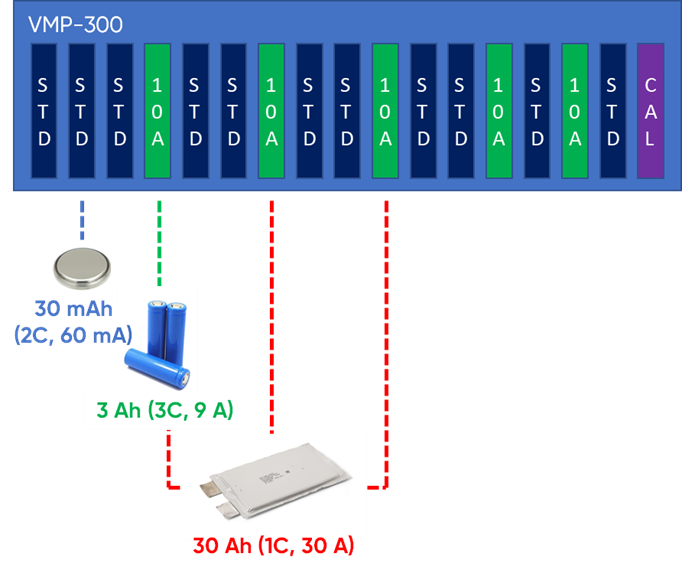
The original example starts with a VMP-300 and a roughly 30 mAh LIR2032 coin cell, for which a standard channel can be suitable within its operating limits.
For a 3 Ah cylindrical cell, a 3C test requires 9 A and can justify a 10 A booster. A 30 Ah pouch cell tested at 1C requires 30 A, illustrated here by three compatible 10 A boards. Capacity or cell shape alone does not determine the booster: C-rate and voltage window are also needed.
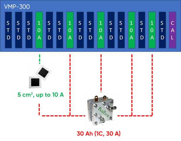
In the historical PEMFC example, a target current density of 2 A/cm² requires 10 A for 5 cm² active area and 50 A for 25 cm². The latter illustrates five compatible 10 A boosters in parallel. This is a sizing example, not a universal fuel-cell current density.
Parallel operation and slot limits
Only supported boosters of the same type may be combined in parallel. Do not mix a 2 A model with a 10 A model to obtain a combined voltage/current capability. Two identical supported boards can double available current; parallel operation does not increase the voltage window.
The illustrated VMP-300 arrangement uses one controlling channel and up to fifteen 10 A boosters: sixteen slots in total and up to 150 A. This is not the limit for every Premium chassis or board type.
EC-Lab recognises supported configurations, but wiring, ranges, cell limits and channel assignment still require checking before use.
EIS at high power
The usable EIS range depends on the booster, current, voltage, cell impedance and wiring. Do not transfer the unboosted potentiostat’s maximum frequency automatically to a high-current configuration. See the manufacturer discussion of EIS data quality on high-power systems.
This revised local article is based on the original account of Premium internal boosters. Confirm the selected combination with the local representative before configuring a system.