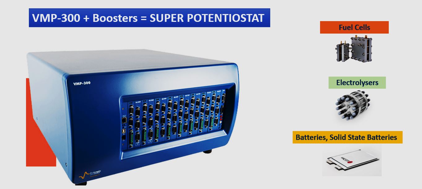
What distinguishes the VMP-300?
The VMP-300 is a sixteen-slot instrument in BioLogic’s Premium family. Channel boards and boosters occupy slots, so increasing current capability can reduce the number of independently controlled experiments.
Specify required current, voltage window, low-current measurements, EIS range and simultaneous experiments separately. The original article quoted a 7 MHz EIS upper limit; the current product page describes capability up to 11 MHz in an appropriate configuration. Acquisition at 1 µs requires the ARG option. Do not interpret a ULC low-current figure as accuracy for a 150 A booster arrangement: resolution, sensitivity, accuracy and maximum current are separate specifications.
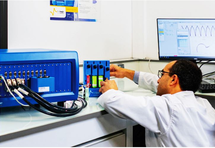
The sixteen slots accept the chosen channel boards and internal boosters. The historical booster list comprises ±1 A/±48 V, ±2 A/±30 V, ±4 A/−3 to +14 V and ±10 A/−1 to +6 V. Confirm board compatibility, actual control range and EIS option when ordering.
An instrument can be expanded progressively. An EIS-capable channel may, for example, investigate a roughly 30 mAh LIR2032 cell within suitable current and voltage limits. Supported two-, three-, four- and five-wire connections do not always correspond to that many distinct electrodes. Channel hardware and software jointly determine available techniques.
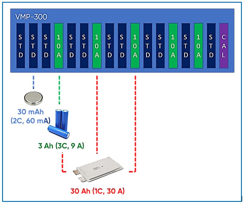
Slot allocation: independent channels versus current
Possible sixteen-slot layouts with identical supported 10 A boosters include:
- 1 × 150 A: one controlling channel and fifteen boosters, sixteen slots.
- 2 × 60 A: two channels and two groups of six boosters, fourteen slots.
- 3 × 40 A: three channels and three groups of four boosters, fifteen slots.
- 4 × 30 A: four channels and four groups of three boosters, sixteen slots.
- 8 × 10 A: eight channels and eight boosters, sixteen slots.
Rearranging supported boards changes channel count and available current per channel. Twelve 10 A boosters can form four 30 A groups, two 60 A groups or one 120 A group. Follow the installation procedure and use the required connection accessories. Parallel operation increases current capacity, not voltage range; do not combine different booster types arbitrarily.
Evaluate accuracy for the selected current and voltage ranges. Check required cell voltage, including operation near 0 V for fuel cells, against the actual booster window. 150 A and 100 kHz are not a universal simultaneous specification for every arrangement: the supported EIS window requires configuration and cell-impedance checks.
External devices can use supported analogue, digital and software interfaces. Verify EXTAPP, LabVIEW/Python and temperature-controller integration against the actual connection. The historical I/O list is not a wiring guide for every system.
Shared access and multielectrode experiments
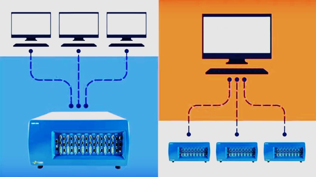
Ethernet access allows users on different computers to work with appropriate channels of a shared instrument. One computer can also control multiple supported instruments, for example in a sample-testing workflow.
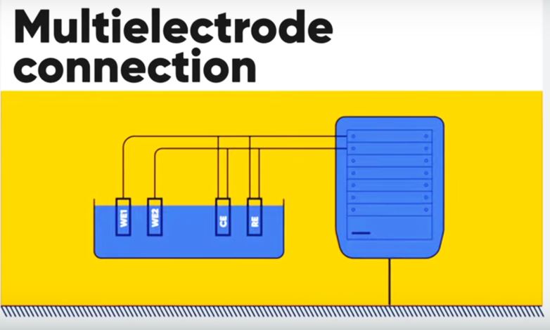
“Modify on the fly” permits supported EC-Lab parameters, such as certain voltage limits, to change during acquisition. Consider the technique, cell limits and documentation when making changes.
EC-Lab acquisition and analysis
EC-Lab connects acquisition, analysis and display. Check installation and updates through manufacturer support. The old article’s USB-drive delivery description is not a promise about current distribution; the quotation defines the software package and integration options.
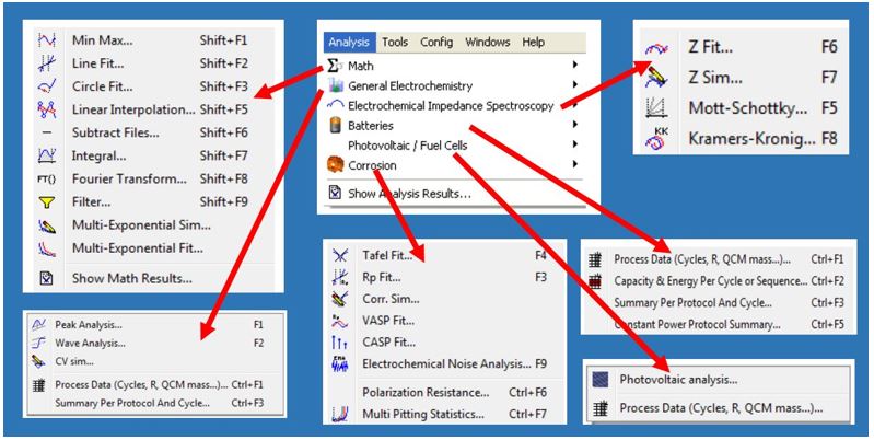
The earlier account described more than eighty techniques. Available methods depend on software release and hardware options.
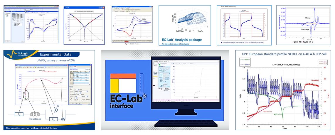
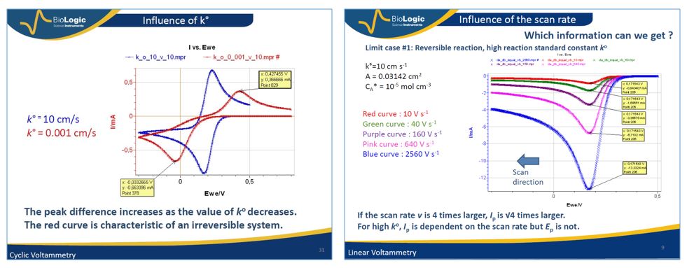
EIS and CV simulation can explore how parameters affect spectra and voltammograms.
Useful information and reliable acquisition
Processing time, current, charge, cycle and potential data supports capacity, Coulombic-efficiency, dQ/dV, ohmic-drop, Tafel and CV-peak analysis. Each requires an appropriate protocol and valid model.
A program and limits loaded onto the channel can reduce dependence on continuous PC communication. This is not a universal guarantee of data retention, buffer capacity or unlimited autonomous operation. Before a long experiment, check the specific instrument’s disconnection behaviour and data-saving arrangements.
Communication loss, PC shutdown and loss of instrument power are different failure scenarios. Document an appropriate procedure for each.
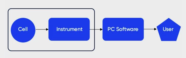
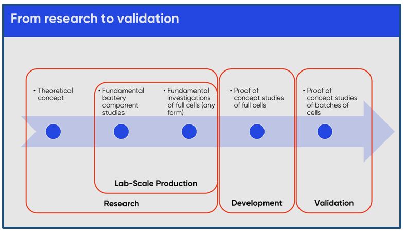
Different VMP-300 configurations can support research and prototype testing. A high-current configuration does not automatically provide sixteen independent high-current channels. Accuracy, data handling and acceptance criteria require validation for the actual task. The retained illustration shows stages from research to validation.
These examples preserve the original author’s account. They are not a new verification of the institutions’ current equipment or projects.
The author described a VMP-300 used by the Renewable Energy Research Group at the Research Centre for Natural Sciences. The reported work included catalytic activity, catalyst surface area, corrosion and membrane-resistance measurements. Complete fuel cells were tested using an FCT-150 station, while a VMP-300 with boosters supplied the required CV capability.
According to that account, a 10 A booster served small 5 cm² cells; experiments with 16 cm² cells required further boosters. When studying stacks, multichannel measurements helped examine individual cells alongside the whole assembly. The author reported the combined FCT-150/VMP-300 setup as useful for this work.
The same 2023 account described the Solid-State Energy Storage Research Group’s work on functional materials for solid-state and conversion-electrode lithium-ion batteries, post-lithium systems such as sodium and magnesium, and coupled electrochemical/mechanical ageing. This work required many channels and long experiments. The account highlighted high-frequency EIS around 100 kHz for processes of interest in solid-state materials; that frequency is not a universal assignment of a grain-boundary mechanism.
The author reported adding four channel boards to free positions in the Renewable Energy group’s chassis, allowing the two groups to share the instrument.
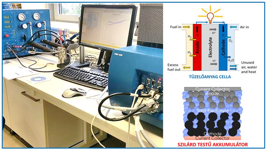
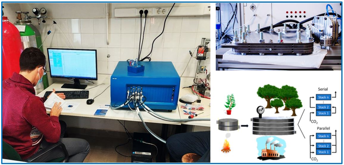
Electrolysers, fuel cells and batteries create different requirements for energy-conversion and storage measurements. Prototype work can require currents beyond a standard channel’s capability, making modular expansion relevant.
The configurations above illustrate the trade-off between independent channel count and current. Board allocation, voltage window, EIS requirements and experimental protocol jointly determine suitability. Contact the local team at info@labornite.hu to discuss a specific configuration.